PCANFD Series
1. Product Introduction
The PCAN-FD series is a USB-to-CAN FD adapter designed for high-performance automation and in-vehicle networks. It is fully compatible with original protocols, supporting bit rates up to 12 Mbit/s, and backward compatible with CAN 2.0 A/B.
1.1 Core Advantages
- Ultra-high Bandwidth: Maximum 64 data bits per CAN FD frame, maximum transmission rate up to 12 Mbit/s
- Smart Configuration: Supports toggling 120惟 terminating resistor via software
- Full-stack Compatibility: Seamlessly integrates with PCAN-View, PCAN-Explorer, and PCAN-Basic API
2. Hardware Specifications
2.1 Model Quick Selection
| Model | CAN Version | CAN Channels | CAN Max Bit Rate | Electrical Isolation | Special Features |
|---|---|---|---|---|---|
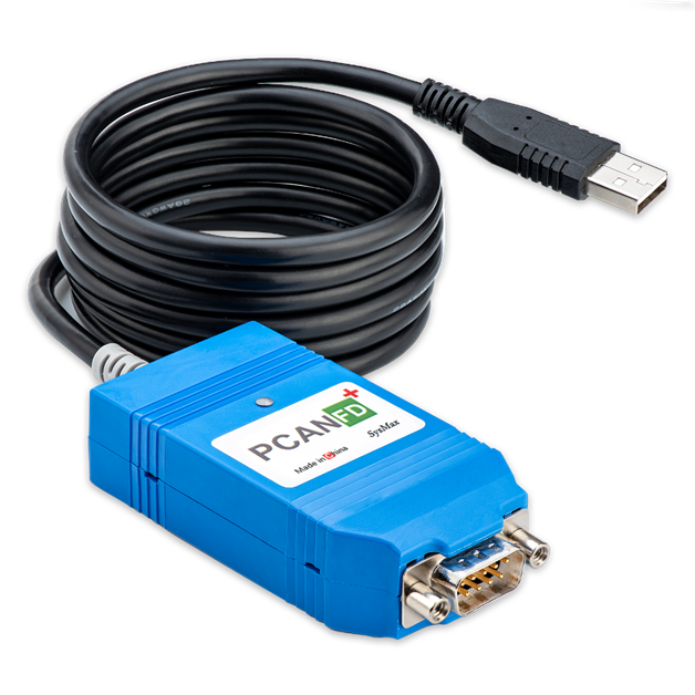
| PCAN-FD+ | CAN FD | 1 | 8 Mbit/s | 1500 Vrms | Controllable resistor, firmware upgrade |
| PCAN-FDC+ | CAN FD | 1 | 12 Mbit/s | 1500 Vrms | High-performance ceramic oscillator, controllable resistor, firmware upgrade |
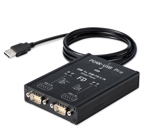
| PCAN-Pro FD (8M) | CAN FD | 2 | 8 Mbit/s | 1500 Vrms | Dual-channel, controllable resistor, firmware upgrade |
| PCAN-Pro FD (12M) | CAN FD | 2 | 12 Mbit/s | 1500 Vrms | Dual-channel, high-performance, controllable resistor, firmware upgrade |

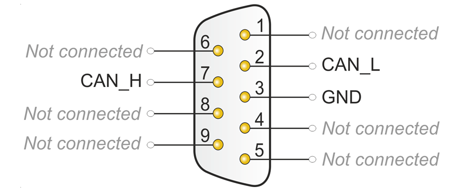
2.2 Physical Interface Definitions (DB9)
This product connects to CAN bus through 9-pin D-Sub interface. Pin assignment complies with CiA庐 303-1 standard:
| Pin | Signal | Description |
|---|---|---|
| 2 | CAN_L | CAN Low |
| 7 | CAN_H | CAN High |
| 3 | GND | Ground |
| Others | NC | Not connected |
3. Core Features
3.1 Hardware Features
- USB Compatibility: Supports USB full-speed mode, compatible with USB 1.1, USB 2.0, USB 3.0
- Electrical Safety: Built-in 1500 Vrms electrical isolation, effectively resists industrial environment surges
- Interface Standard: CAN bus connection through 9-pin D-Sub interface (complies with CiA庐 303-1)
- Terminating Resistor: Supports software-controlled internal 120惟 terminating resistor (no disassembly required)
3.2 Protocol Support
- CAN Protocol: Supports high-speed CAN connection (ISO 11898-2) and CAN FD (supports ISO and non-ISO switching)
- Bit Rate Adjustment: 25 Kbit/s ~ 12 Mbit/s
- CAN Format: Compatible with CAN 2.0A (11-bit ID), 2.0B (29-bit ID)
- Time Stamp: Hardware-level time stamp with resolution up to 1 渭s
3.3 Software Ecosystem
- API Compatibility: Fully compatible with PCAN FD API, seamlessly integrates with PCAN-View, PCAN-Explorer
- Bus Monitoring: Supports bus load measurement, error frame detection, and bus status monitoring
- Firmware Upgrade: Supports online firmware upgrade, continuously optimizing performance
- High-performance Real-time Processing: Suitable for application scenarios requiring high data transmission rates
3.4 Multi-system Support
Windows
- Windows 11, Windows 10, 8.1, 7 (32/64-bit)
- Windows CE 6.x (supports x86 and ARMv4 processors)
Linux
- Linux (32/64-bit)
- Linux kernel includes driver (SocketCAN)
MacOS
- Supports MacCAN library
4. Operation Instructions and Indicator LEDs
4.1 Driver Installation
鈿狅笍 Important: Must follow the principle of "install driver first, then plug in hardware".
- Obtain driver compressed package
PEAK-System_Driver-Setup.zipfrom the provided cloud drive materials - Extract and run
PeakOemDrv.exe, accept defaults to complete installation - Plug device into USB interface, confirm
CAN-Hardware -> PCAN-USB FDappears in "Device Manager" - Check adapter LED status, after driver successfully recognizes the device, refer to
4.2-Indicator LED Logicsection for indicator status
4.2 Indicator LED Logic
PCAN-FD series adapters use dual-color indicators to define device status. Please first confirm your product batch, refer to your specific model:
4.2.1 Batch: 24-7 and later (Blue/Green dual-color LED)
| Device Status | Terminating Resistor: Off (Default) | Terminating Resistor: On |
|---|---|---|
| Driver not recognized | 馃數/馃煝 Blue/Green alternating flashing | 馃數/馃煝 Blue/Green alternating flashing |
| Driver recognized, CAN off | 馃數 Blue constant on | 馃煝 Green constant on |
| Driver recognized, CAN on | 馃煝 Green constant on | 馃數 Blue constant on |
| Data transceiving (Tx/Rx) | 馃煝 Green fast flash: Transmit (Tx) 馃數 Blue fast flash: Receive (Rx) | 馃煝 Green fast flash: Transmit (Tx) 馃數 Blue fast flash: Receive (Rx) |
4.2.2 Batch: Before 24-7 (Red/Green dual-color LED)
| Device Status | Terminating Resistor: Off (Default) | Terminating Resistor: On |
|---|---|---|
| Driver not recognized | 馃敶/馃煝 Red/Green alternating flashing | 馃敶/馃煝 Red/Green alternating flashing |
| Driver recognized, CAN off | 馃煝 Green constant on | 馃敶 Red constant on |
| Driver recognized, CAN on | 馃敶 Red constant on | 馃煝 Green constant on |
| Data transceiving (Tx/Rx) | 馃敶 Red fast flash: Transmit (Tx) 馃煝 Green fast flash: Receive (Rx) | 馃敶 Red fast flash: Transmit (Tx) 馃煝 Green fast flash: Receive (Rx) |
Transceiver indicator LED colors will superimpose on constant on indicator color
5. Connecting to CAN Bus
5.1 Terminating Resistor Management (Software Control)
High-speed CAN bus (ISO 11898-2) must configure 120 ohm terminating resistors at both ends of the bus. Terminating resistors prevent reflection of interference signals, ensuring normal operation of transceivers connected to CAN nodes (CAN interfaces, control devices).
PCAN-FD series supports enabling internal resistor through SysMax_PCAN_Tool, no disassembly or external connection required:
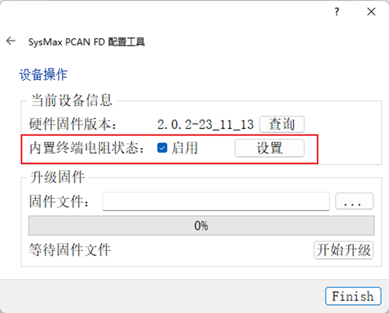
Operation Steps
- Open SysMax_PCAN_Tool configuration tool
- Select the corresponding hardware ID
- Check "Enable"
- Click "Set", observe device light feedback
鈿狅笍 Note: PCAN-FD defaults to built-in terminating resistor disabled to meet the need for direct connection to bus that already includes terminating resistor for use.
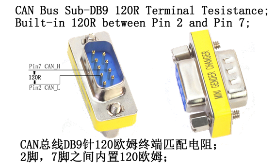
5.2 External Terminating Resistor
If you need external terminating resistor, you can contact your supplier to purchase terminating resistor accessories compatible with 9-pin D-Sub interface.
7. Supply List and Resource Download
7.1 Supply List
- PCAN-FD adapter
- DB9 wiring terminal adapter
- Data disc/QR code
- Flathead screwdriver
- DB9 terminating resistor (120惟) (optional)
7.2 Software and Drivers
- Device drivers for Windows 10, 8.1, 7 and Linux (32/64-bit)
- CAN monitor software
- SysMax_PCAN_Tool configuration tool (for terminating resistor control)
- PDF format manual
7.3 Development Resources
- Programming interface for developing applications with CAN connection
- Programming interface for automotive industry standardized protocols
- Linux SocketCAN driver (kernel integrated)