SM1610 Native Driver Solution
1. Product Overview
1.1 Product Introduction
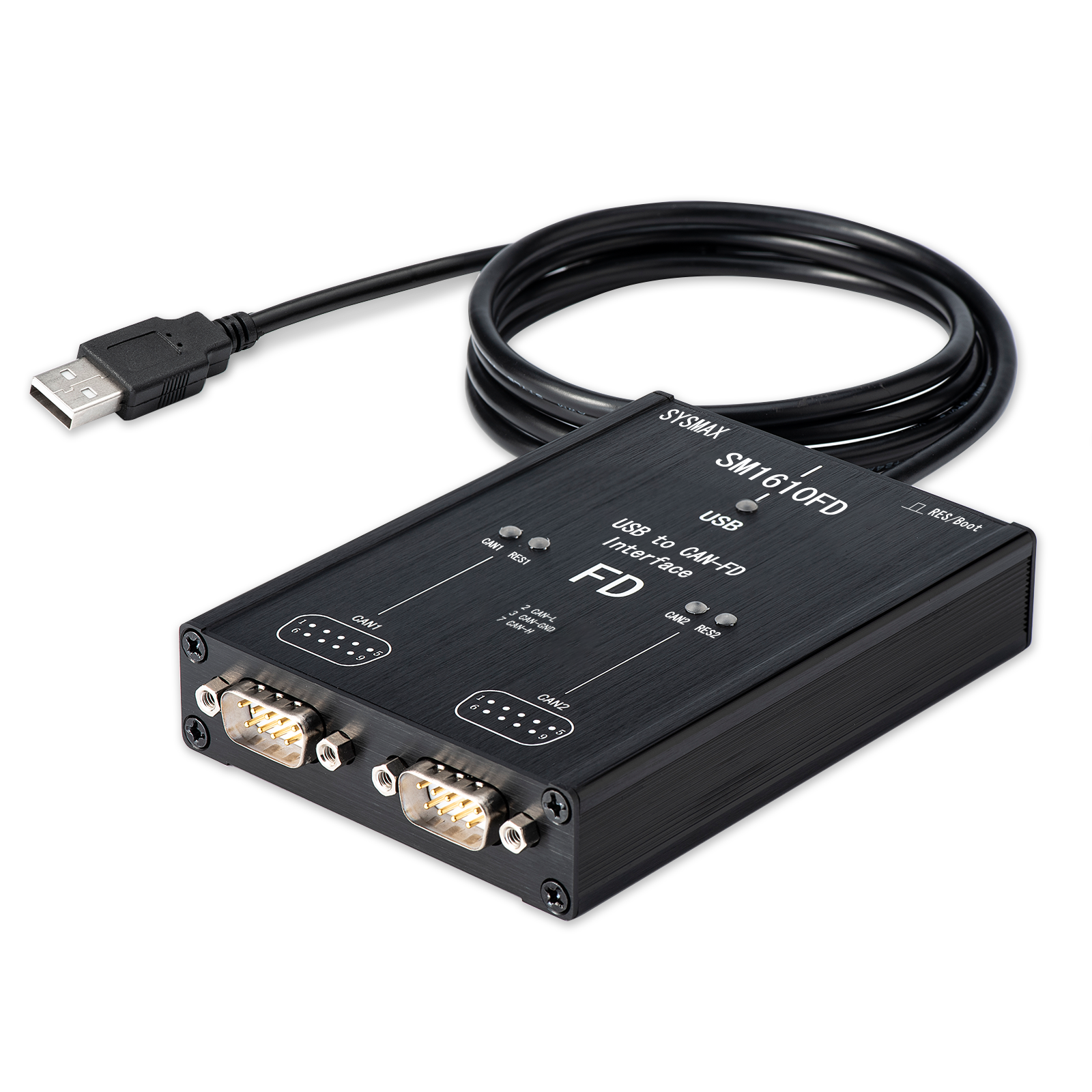
SM1610 is a high-performance automotive network interface device launched by Snowball Electronics, designed as a domestic alternative to Germany's Vector VN1610. Unlike the "protocol conversion/bridging" solutions on the market, SM1610 uses a native Vector driver interface that can be directly recognized by the Vector toolchain, providing extremely low latency and high reliability in-vehicle communication experience.
1.2 Core Advantages
- Native driver support: No need to install intermediate conversion software, directly integrates into Vector hardware ecosystem

- Dual-channel CAN FD: Supports 2 independent CAN FD channels with maximum bit rate up to 10 Mbps (LIN not supported)
- Advanced diagnostic functions: Supports error frame injection and real-time error status display, meeting complex R&D requirements

- Built-in controllable terminating resistor: Built-in self-controllable 120 惟 terminating resistor, supports remote firmware upgrade
2. Software Ecosystem and License Information
2.1 Software Compatibility
Since SM1610 is fully compatible with the Vector XL Driver Library interface, it supports the following software environments:
| Category | Compatible Software | Requires Additional License (LIC) |
|---|---|---|
| Vector commercial software | CANoe, CANape, CANalyzer (supports v13 and above) | Yes (must have hardware Key or software license) |
| Secondary development interface | vxlapi.dll, python-can (Vector interface mode) | No (API development is typically free) |
| Third-party simulation tools | TSMaster, BusMaster, ECUBUS pro | No (basic functions are free to use) |
2.2 鈿狅笍 Important License Statement
[Important!!!] SM1610 hardware does not include any Vector commercial software License authorization. Users must resolve paid software LICs such as CANoe and CANape themselves.
Ways to obtain authorization:
- Search for the required software name on Xianyu or other methods
- Purchase genuine software licenses (LIC) or separate software keyman
- Contact us to obtain CANoe 13 evaluation version for short-term device testing
2.3 Application Scenarios
- Automotive electronics development and testing
- In-vehicle network diagnostics
- ECU calibration and programming
- Automotive electronics R&D verification
3. Hardware Specifications and Interfaces
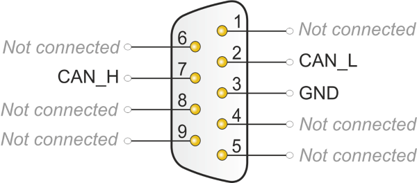
3.1 Physical Pin Definitions (DB9)
SM1610 provides two standard 9-pin D-Sub interfaces, corresponding to CAN 1 and CAN 2 respectively.
| Pin | Signal | Description |
|---|---|---|
| 2 | CAN_L | CAN Low signal line |
| 7 | CAN_H | CAN High signal line |
| 3 | GND | Ground |
| 1, 4-6, 8-9 | NC | Not connected (do not connect) |
4. Indicator LED Logic and Operation Guide
4.1 Status Indicator (Status)
| LED Behavior | Meaning |
|---|---|
| Red/Green alternating flashing | Driver not recognized, please check Vector driver version |
| Green constant on | Driver recognized successfully, device is in ready state |
4.2 Channel and Resistor Indicators
Each channel is equipped with an independent LED group for real-time monitoring of physical layer status.
Channel Status (CH1/CH2)
| Status | LED State | Description |
|---|---|---|
| Off | - | Channel not opened in software |
| Green constant on | 馃煝 | Channel activated in software (e.g., CANoe) |
| Blue fast flashing | 馃數 | Data transmitting/receiving (Tx/Rx) |
| Red fast flashing | 馃敶 | Bus error frame detected |
When the device enters BOOT mode, CAN2 transceiver indicator remains blue fast flashing, all others except status indicator are off.
Resistor Status (R)
| Status | LED State | Description |
|---|---|---|
| Off | - | Built-in 120 惟 terminating resistor disconnected |
| Yellow constant on | 馃煛 | Built-in 120 惟 terminating resistor connected |
4.3 Physical Button Functions
The top of the device is equipped with function buttons for quick hardware configuration:
| Operation | Function | Description |
|---|---|---|
| Short press | Toggle built-in resistor | Cycle through built-in resistor modes (only effective when channel is not activated) |
| Long press (3s) | Enter BOOT mode | For firmware upgrade (at this time CAN2 indicator blue flashes), restart power to exit |
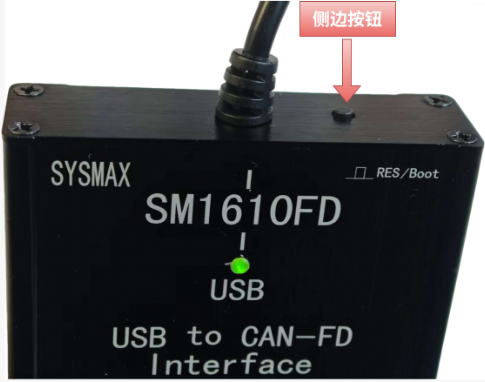
When any channel is open, the button will be locked.
5. Quick Start: Driver Installation
To ensure the device is correctly recognized, please strictly follow these steps:
[Very Important!!!] Please download and install the following driver version, then restart and confirm in Device Manager that the driver version matches the image below 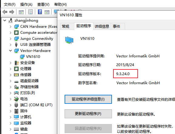
5.1 Driver Installation
Download driver Driver download link: https://bj4633.apps.aliyunfile.com/disk/s/fnyzgJGvrc4?domainId=bj4633
Install driver
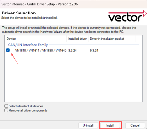
- After extracting the compressed package, double-click setup.exe to install the driver.
- Note to check the device type on the following page, select installation, keep default settings for other steps.
Verify driver installation
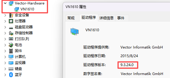
- Open Device Manager, driver recognizes the device, installation complete.
- Confirm status light is green constant on, indicating device has been correctly recognized.
5.2 Hardware Connection
SM1610 supports dual-channel use, using two 9-pin D-Sub as interfaces, corresponding to Vector CAN1 and Vector CAN2 channels respectively.
6. Software Configuration
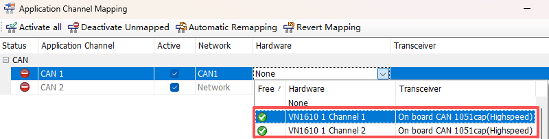
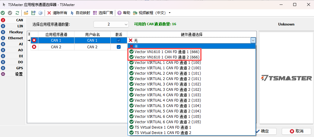
6.1 Channel Selection
CANoe
TSMaster
6.2 Firmware Upgrade
For detailed firmware update process, please refer to: TODO
7. FAQ (Troubleshooting)
Q: After opening the channel, bus error occurs and light turns red?
A:
- Check if bit rate configuration is consistent
- Confirm if necessary built-in resistor is enabled
- Check if cable connection is correct
Q: Why can't the button toggle resistor?
A:
- When channel is running (green constant on), the button is locked
- Please stop measurement in software first, then perform resistor toggle operation
Q: Device not recognized?
A:
- Check USB cable connection
- Confirm Vector driver is correctly installed
- Check if Vector Hardware node appears in Device Manager
8. Technical Support
8.1 Contact Information
- Technical support WeChat: sysmax-cn sysmax-ts
- Product documentation: https://gitee.com/sysmax/sysmax-main
This document is continuously being updated, please provide feedback if there are any issues